Confined Disposal Facility (CDF)
The Confined Disposal Facility (CDF) was constructed in stages from 2002–2011 to store the contaminated sediment from the Indiana Harbor and Canal (IHC) that is removed by dredging.
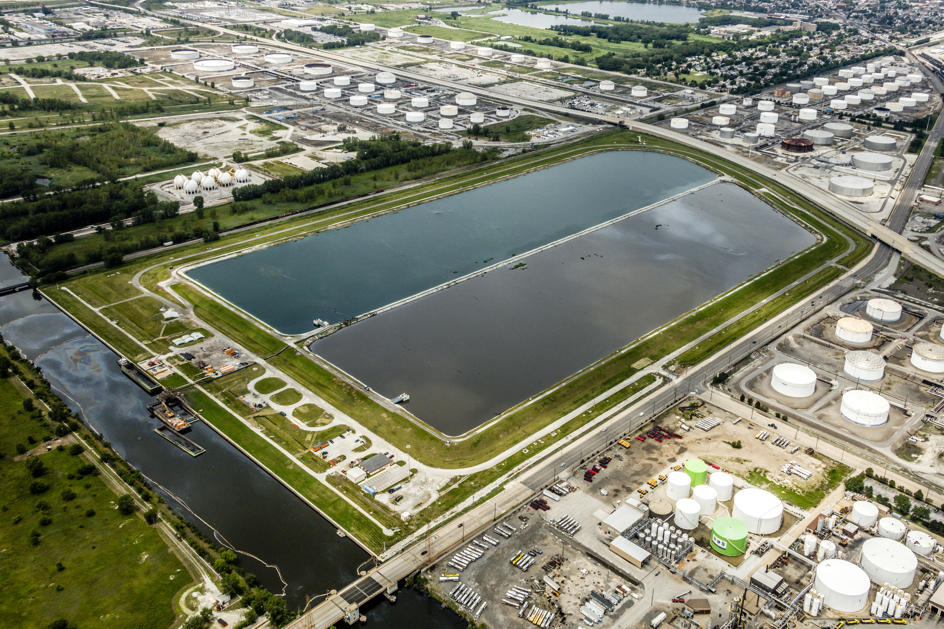
The CDF was designed to safely contain contaminated dredged sediments from the Indiana Harbor and Canal (IHC) onsite. It is located on a USEPA Resource Conservation and Recovery Act (RCRA) site in East Chicago, Indiana, on the Lake George Branch of the IHC. See the CDF Site History page for more information about the former refinery site on which the CDF was built.
Dikes of impervious clay material contain the dredged sediments. The center dike separates two “cells”, sometimes referred to as the “east cell” and the “west cell”.
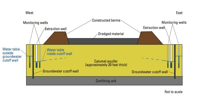
A water treatment plant at the CDF treats sediment water, groundwater, and precipitation that accumulates in the CDF before it is discharged back to the Lake George branch of the canal. Three components work together to maintain an inward gradient to prevent groundwater from flowing away from the CDF site: a gradient control system, a groundwater cutoff wall, and a sealed sheet pile cutoff wall.
Legacy Issues and CDF Measures
The following table lists some issues encountered on the former refinery site, and the measures taken to address them at the CDF.
Legacy Issue |
Measures Taken |
|---|---|
| Free product on groundwater (e.g., oil) |
|
| Extensive soil contamination |
|
| Buried waste and debris left on former refinery site |
|
| Poor groundwater and surface water quality |
|
| Poor regional air quality |
|
CDF Features
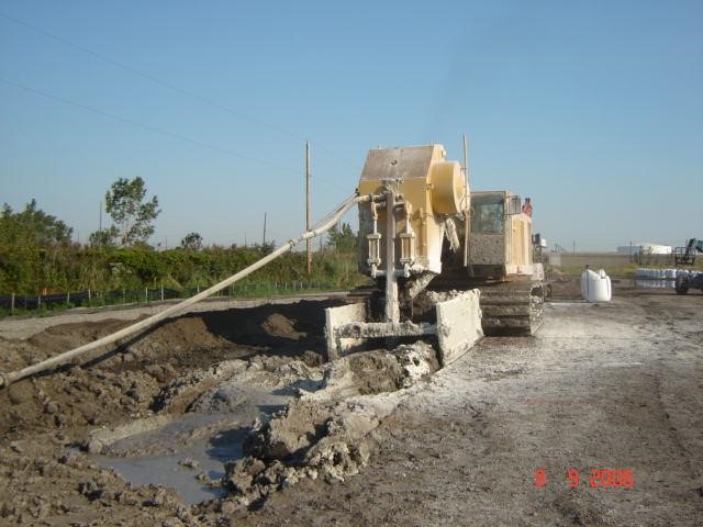
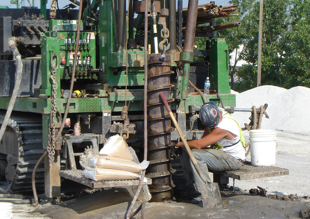
Slurry cutoff wall
The slurry cutoff wall is an underground clay wall approximately 40 feet deep around the perimeter of the CDF on the north, east, and west sides. Made of a soil bentonite slurry, it hydraulically isolates the groundwater at the site from the rest of the Calumet aquifer.
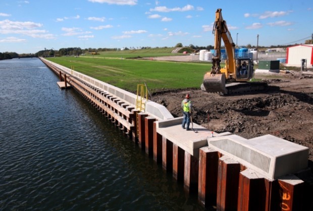
Sealed Sheet Pile Cutoff Wall
A sealed sheet pile cutoff wall at the canal on the south side of the site hydraulically isolates the groundwater at the site from the Lake George Branch of the IHC.
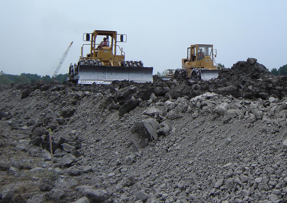
Clay dikes
Approximately 20-ft tall clay dikes hold the dredged material, and a 14-ft high center dike aids sediment and water management. The dikes may be raised in the future to accommodate more dredged material. The center dike separates the two CDF cells.
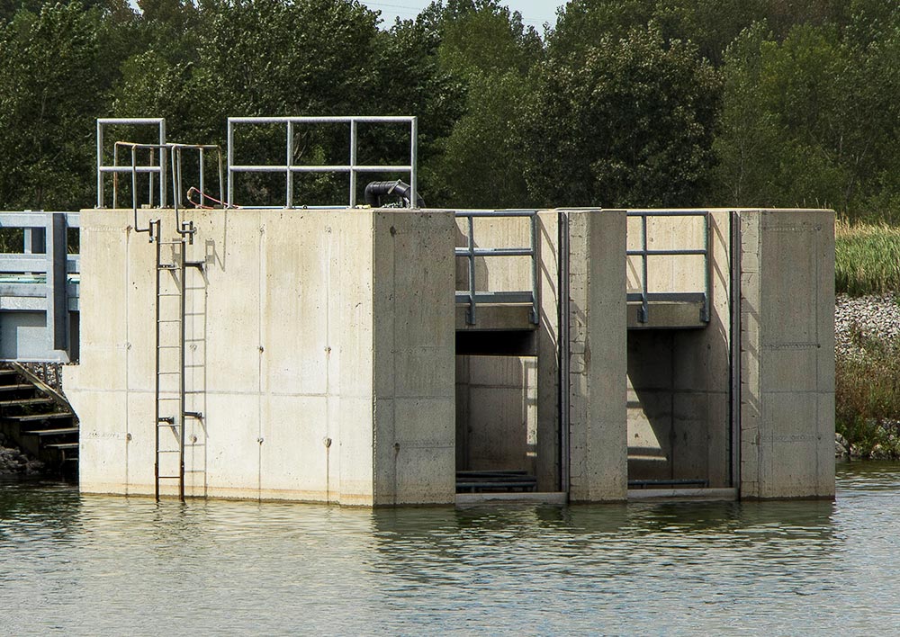
Decant structures
Two decant structures in the CDF (one in each cell) can be used to control the water levels in the CDF. The decant structures can also be used minimize suspended solids in water to be pumped to the onsite treatment plant. This photo shows the inspection of the inside of one of the decant structures.
Gradient control system
The gradient control system pumps groundwater from the CDF to the CDF east cell and eventually to an onsite water treatment plant. The system consists of 96 vertical extraction wells that help to prevent offsite migration of contaminated groundwater from the former refinery site.
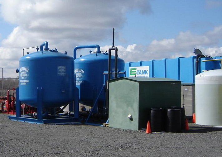
Water treatment plant
The water from the CDF is a combination of groundwater, dredge water, and precipitation. The water treatment plant treats water from the CDF cells to levels permitted for discharge back into the canal.
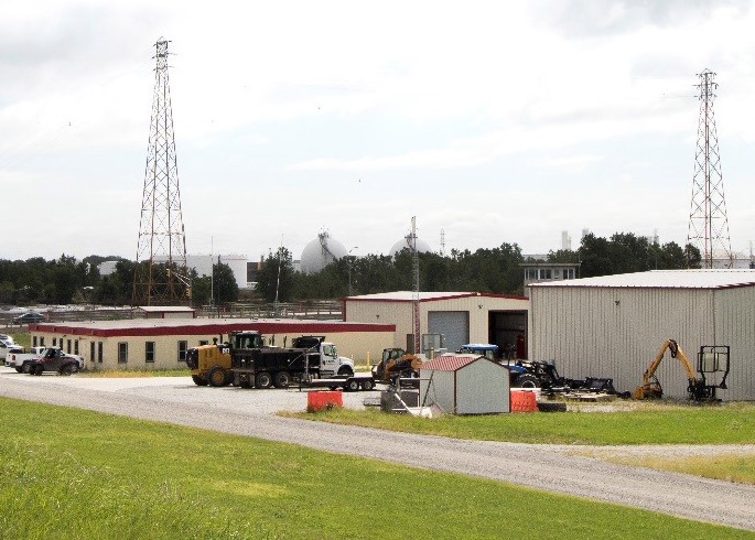
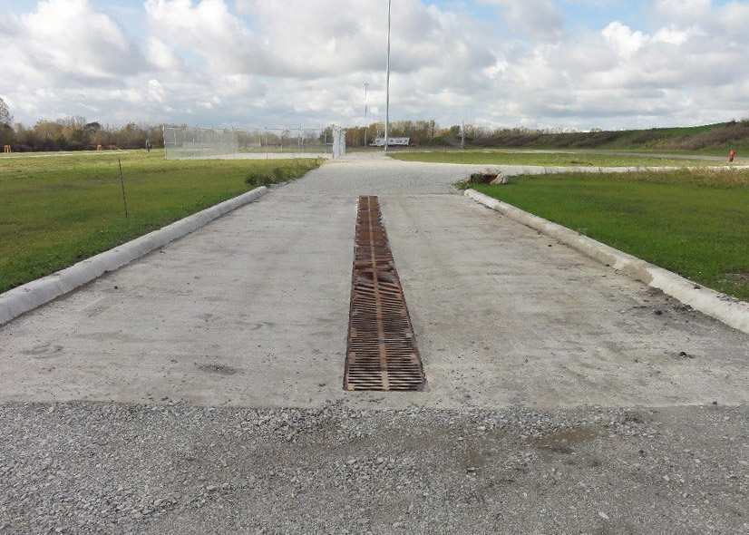
Other supporting features
Dredging off-load facilities, an administration building and parking lot, security features, storage facilities, decontamination pads (stations), and other support features have been constructed as necessary.
RCRA
The CDF is a Resource Conservation and Recovery Act (RCRA) facility. The site requires RCRA corrective action due to the contamination of soil and groundwater on site from past industrial activities.
The CDF site currently has open RCRA status because the court-approved closure of the facility was not comparable to a RCRA-approved closure. The CDF design incorporates the “corrective action” for the pollutants left on the former ECI site. The gradient control system and cutoff walls are intended to meet the permeability requirements of 10-7 cm/s for the CDF perimeter.
Site Closure
The future planned total capacity of the IHC CDF is 4.8 million cubic yards after the extension of the perimeter dikes. This extension is designed to provide adequate sediment storage capacity for the design life. The facility will undergo RCRA closure after it no longer accepts dredged material. RCRA closure will include final clay cap (RCRA cap) that will maximize surface runoff from precipitation and minimize the amount of infiltration and percolation of water into the CDF. The final cap design will meet the regulatory requirements at the time of site closure.
Additional photos of the CDF are available for viewing in the Photo Gallery. Learn about the CDF construction history.
