Gradient Control System (GCS)
The Gradient Control System (GCS) consists of extraction wells and monitoring wells to prevent against offsite migration of groundwater from the Confined Disposal Facility (CDF) site.
Extraction Wells
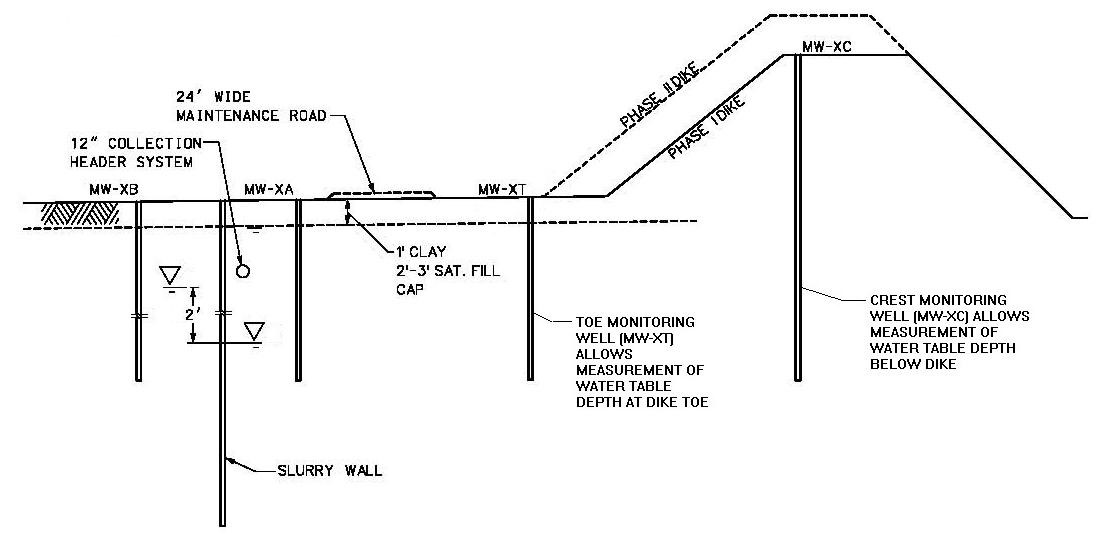
Ninety-six groundwater extraction wells surround the perimeter of the CDF. The extraction wells pump groundwater from the CDF-side of the cutoff wall to the CDF and eventually to an onsite water treatment plant. At any time and any location at the CDF site, the onsite groundwater is approximately at least 2 feet lower on the inside of the cut off wall than outside the wall. This establishes an inward gradient that causes the groundwater and site contaminants to stay inside the wall rather than migrating offsite.
The extraction wells are connected to a pipe that discharges into two lift stations where the groundwater is pumped to the CDF east cell via two pipes that go over the CDF dike. Three types of water mix within the CDF: 1) Groundwater within the CDF cutoff wall confines, 2) Precipitation that falls into the CDF, and 3) The water that comes with the dredge material. This combined water is treated at the onsite treatment plant before it is discharged to the Indiana Harbor and Canal (IHC).
These extraction wells are installed in groups of four to eight wells (22 groups in total). Each group is associated with a pair of monitoring wells that are used to determine when the pumps in the extraction well group should run. The combination of the cutoff wall and inward gradient protects against offsite migration of groundwater. The extraction wells are controlled by an onsite computer.
Monitoring Wells
Monitoring wells enable observation of groundwater levels, which are automatically read by sensors (pressure transducers) and transmitted to a central computer. These wells are installed in pairs (22 pairs in total), one on each side of the cutoff slurry wall (a low-permeability barrier constructed in the ground), for each extraction well group. Groundwater levels between opposite sides of the wall are read by the computer, and pumps are turned on when levels reach a target amount in the associated monitoring well pair.